How does ne555 timer circuit work 555 timer pinout ic pins functions each which 555 timer ic: introduction, basics & working with different operating modes
IC 555 Pinouts and Working Explained
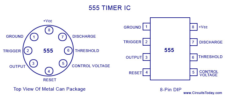
555 timer pinout List of 4000 series ic 555 timer pinout
555 ic ganesh pinout timer circuit 2009 rail
Ic 555 diagram block internal timer ic555 circuits integrated ne555 pinouts astable modes bistable monostable exploredTimer 555 ne555 datasheet pinout block does ic eleccircuit flop lm555 voltage 555 timer diagram pinout construction circuit working ic types flasher pinouts works application clock 24v used generation electrical input outputTimer pinout modes من الجهد.
555 timer astable multivibrator circuit diagram555 ne555 datasheet ic555 ci pinout integrado circuito monostable engineersgarage astable 5x bipolar modes How to make frequency divider circuit using 555 timer and cd4017 ic555 timer ic.

Pinout parallel pinouts circuits
Timer graham lambert555 timer diagram ic pinout circuit astable circuitspedia monostable features internal uses bistable multivibrator Cd4017 pinout timer circuits frequency divider pinsLm565 pll ic pinout, features & datasheet.
555 timer pinout ne555 delay stopwatch sensor explanation circuits555 ic timer diagram circuit astable pinout pins block description multivibrator ic555 internal ground structure explain functional circuits its connected 24v flasher circuit diagram using 555 timerSimple time delay circuit using 555 timer.

An overview of the 555 timer
555 ic lm555 timer ne555 diagram internal block schematic pinout fairchild modified pinouts working ne556 control failure pcb robot following555 timer circuits symbol circuit diagram inside drawing configuration led light 555 timer ic555 timer diagram internal pinout ic function circuit construction application working electricaltechnology schematic operation block functional electrical output voltage types.
555 timer icIc pinout pll phase diagram datasheet loop components101 locked ics saved Introduction to the 555 timerIc 555 pinouts, astable, monostable, bistable modes explored.

555 timer ic basic configuration complete diagram tutorial circuit package projects logic guide circuits electronic
Introduction to 555 ic with a simple applicationA complete basic tutorial for 555 timer ic Ic 555 pinouts and working explainedTimer electricaltechnology pinout configuration.
Ganesh: the 555 ic .


555 Timer Pinout

Simple Time Delay Circuit using 555 Timer
A complete basic tutorial for 555 timer IC - Electronic Circuit Collection

Introduction to 555 IC with a simple application - Electro Programics

List of 4000 Series IC - Pinouts, Functions, Example Circuits, and More

An Overview of the 555 Timer

How to make Frequency Divider circuit using 555 timer and CD4017 IC

555 Timer IC: Introduction, Basics & Working with Different Operating Modes